Adding Forces and Debris
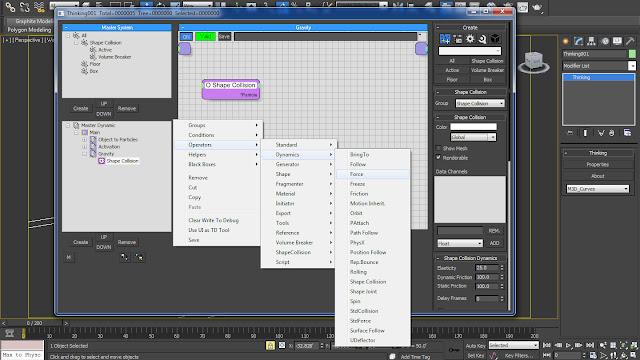
01.1 We will start adding forces by creating a separate dynamic set for each one of them, inside the ‘Main’ dynamic set. Rename this new Dynamic set as Gravity. Bring in the ‘Shape Collision’ Group inside it and Append a ‘Force’ Dynamic Operator to the Particles parameters from the right click menu ‘Operators > Dynamics > Force’.
Fig 01.1
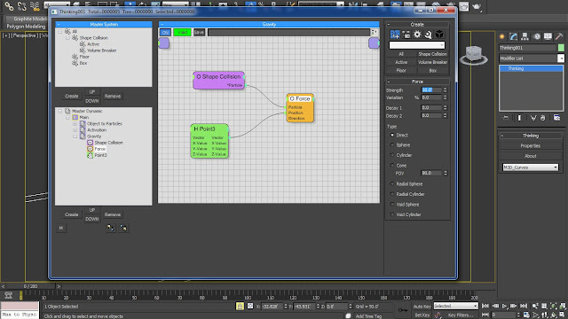
01.2 Now in order to give directions to the force we will create a ‘Point3’ Standard Helper from the right click menu, ‘Helper > Standard > Point3’. Append the Vector parameter of ‘Point3’ Standard Helper to the Position parameter of ‘Force’ Dynamic Operator.
Fig 01.2
01.3 We are going to use the ‘Force’ Dynamic Operator as the gravitational pull and therefore we will bring down the Z-Value to –1.0. Increase the strength of the force operator to 10.0′.
Fig 01.3
02.1 Bring in another Dynamic Set with the name of ‘Wind’ inside the ‘Main’ dynamic set. Bring in the ‘Shape Collision’ Group inside it and Append a ‘Std Force’ Dynamic Operator to the Particles parameters from the right click menu ‘Operators > Dynamics > StdForce’.
Fig 02.1
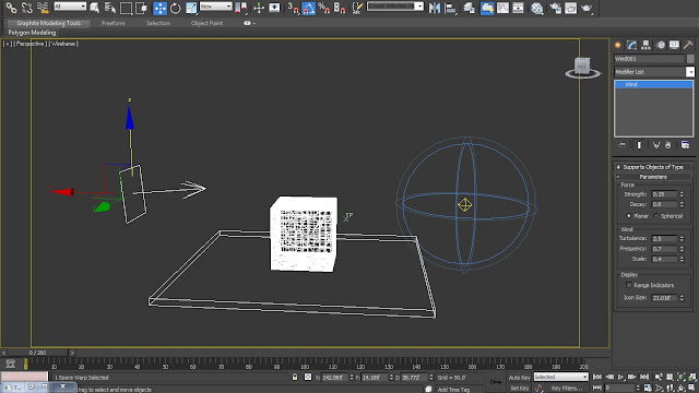
02.2 We will now create a ‘Wind’ force from the Forces roll-out under the Space Warp section of Create panel. Place it right opposite to the ‘Omni’ light and rotate it facing towards the cardboard box. Change the value of Strength to 0.15, Turbulence to 2.5, Frequency to 0.7 and Scale to 0.4.
Fig 02.2
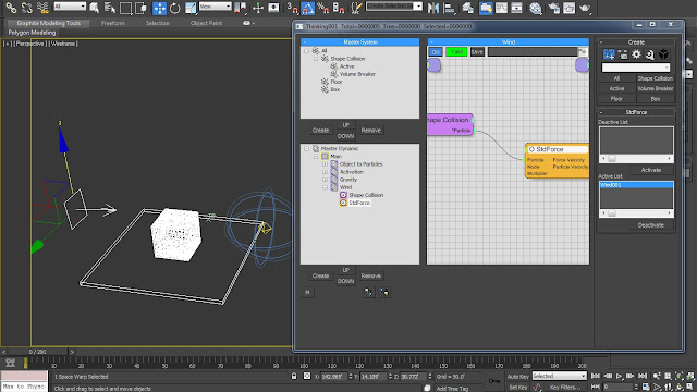
02.3 Connect this ‘Wind’ force to the thinking particles through ‘Bind to Space Warp’. This will bring the Wind force into the ‘Deactive’ List of ‘StdForce’ parameters. Click ‘Activate’ button in order to send the same into ‘Active’ list.
Fig 02.3
02.4 Now we will bring the ‘Float’ Standard Helper that will act as a master controller for multiplying the value of Wind. Right click and select Helpers > Standard > Float and link its ‘Value’ parameter to the ‘Multiplier’ parameter of ‘StdForce’. Increase the Float ‘Value’ to 4.0.
Fig 02.4
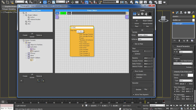
03.1 Add another Dynamic Set into the ‘Main’ with the name of ‘Shape Collision‘. Add a Shape Collision operator into the dynamic set from the right click menu ‘Operators > Shape Collision > SC’. Choose the ‘Shape Collision’ group from the ‘Group’ selection drop-down menu. And choose ‘Floor’ group as the deflector.
Fig 03.1
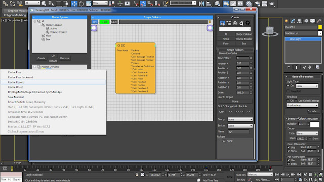
03.2 Before Caching up the scene increase the intensity of ‘Omni’ light to 0.1 in order to increase the region of effect. We are now ready to cache the scene by right clicking on the ‘Main’ Dynamic Set and choosing ‘Cache Record’.
Fig 03.2
03.3 Now if we playback the simulation we will notice the parts of the box flying into the wind. The parts of the cardboard box right now are moving a bit too fast, so in order to slow their pace a bit we will decrease the ‘Dynamic Friction’ and ‘Static Friction’ of the ‘Active’ group to 70.0 each. Also bring down the ‘Dynamic Friction’ and ‘Static Friction’ values of ‘Shape Collision’ Dynamic group to 30.0 each.
Fig 03.3
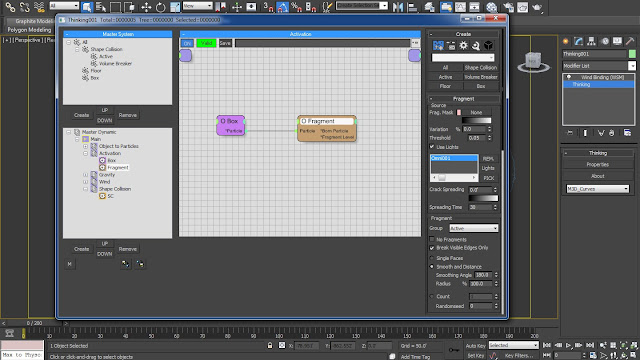
03.4 Select the ‘Fragment’ Dynamic Set under the ‘Activation’ Dynamic Set and enable ‘Smooth and Distance’ option while increasing the ‘Smoothing Angle’ and ‘Radius’ to 180 and 100% respectively.
Fig 03.4
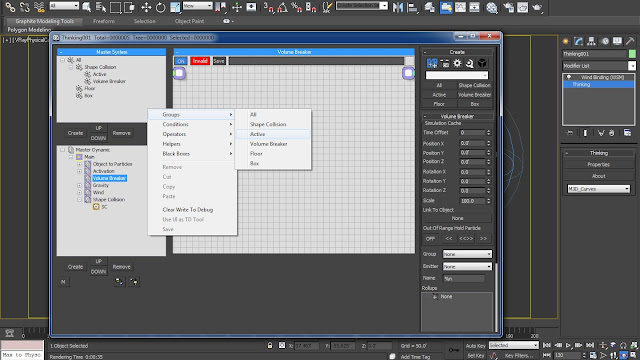
04.1 Now we will continue by adding in another Dynamic Set inside the ‘Main’ Dynamic Set with the name of ‘Volume Breaker’. Add in the ‘Active’ group inside it from the right click menu and selecting ‘Groups > Active’.
Fig 04.1
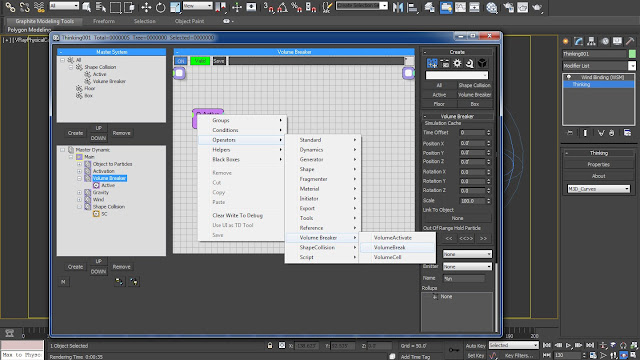
04.2 Also add in a ‘VolumeBreak’ Operator inside the set from the right click menu, ‘Operators > Volume Breaker > VolumeBreak’. As we want to give some randomness to the size of the cardboard box pieces we will not connect it directly to the Active group.
Fig 04.2
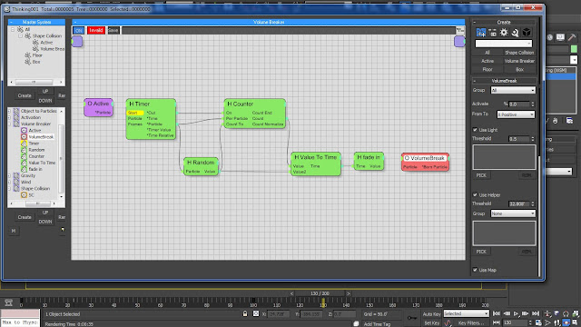
05.1 We will add in a ‘Time Counter’ Black Box to the Dynamic Set again through the right click menu, ‘Black Boxes > M3D_Helpers > Time Counter’. We will get a huge bunch of nodes in the dynamic set, but don’t worry as we are going to get rid of some of them which we don’t require.
Fig 05.1
05.2 Alt + Right Click on ‘H Get Direction’ ‘H Particle Data’ and both the ‘H Float’ nodes in order to get rid of them. Spread the nodes up properly in order to understand the node connections.
Fig 05.2
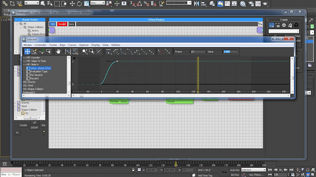
05.3 ‘H Fade In’ will helps us in activating the ‘O VolumeBreak’ Node. Select the ‘H Fade In’ node and dive inside the ‘track view’ of ‘Value’ parameter by right clicking on it and selecting, ‘Show in Track View’. The Bezier curve inside it contains 3 nodes which is Deactivating the whole function after activating it for some time. So in order to keep the whole function active we have to delete the last node and change the value of second node from 0.993 to 1.0.
Fig 05.3
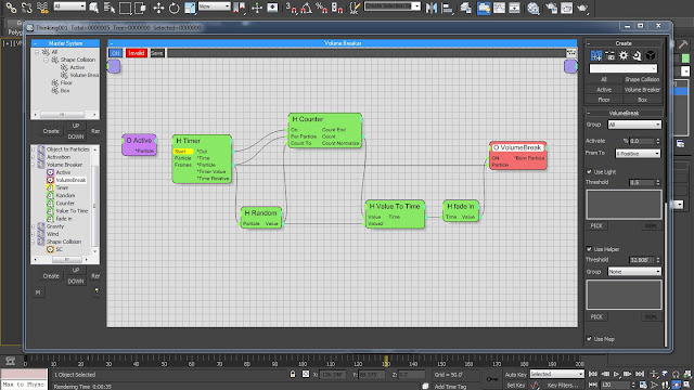
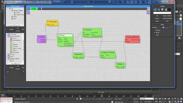
06.1 Click on the Green Input of ‘O VolumeBreak’ Node and select ‘ON’, to get the ‘ON’ function inside its input. Link this ‘ON’ function with the ‘Value’ function of ‘H Fade In’ node in order to activate Volume Breaker. Also connect the ‘Particle’ input of ‘O VolumeBreak’ Node to the ‘Particle’ output of ‘H Timer’ node.
Fig 06.1
06.2 Bring in a ‘Threshold’ Standard Condition inside the Dynamic Set from the right click menu ‘Conditions > Standard > Threshold. Activate the ‘Velocity’ Output of the ‘O Active’ group and pipe it into the ‘Value’ input of ‘Threshold’ node.
Fig 06.2
06.3 Inside ‘Threshold’ parameters increase the ‘Threshold 1’ value to 5.0 and link its ‘Out’ value to the ‘Start’ value of ‘H Timer’ node. Connect the ‘Particle’ values of ‘O Active’ and ‘H Timer’ nodes. Decrease the value of ‘Frames’ inside the ‘H Timer’ parameters to 10, as lots of frames means lots and lots of geometries which can slow down the processor.
Fig 06.3
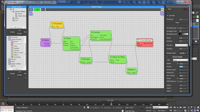
07.1 Select the ‘O VolumeBreak’ node and select ‘Volume Breaker’ group from the ‘Group’ drop down menu. Increase the ‘Activate’ value parameter to 55% and decrease the ‘Raster’ value parameter to 12%. Increase the ‘Density’ value parameter to 5000.
Fig 07.1
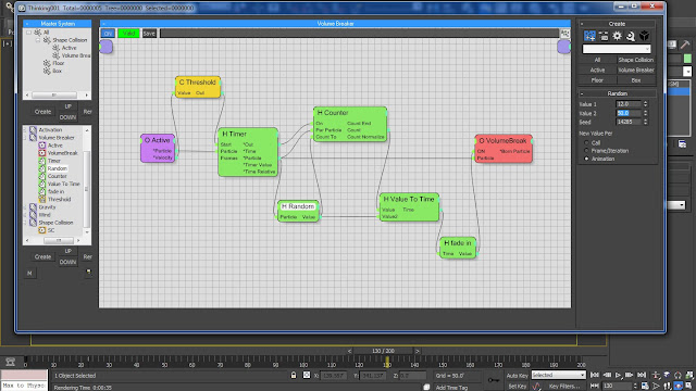
07.2 We can also give some randomness to the function by changing the ‘Value 1’ and ‘Value 2’ parameters of ‘H Random’ node to 12.0 and 50.0 respectively.
Fig 07.2
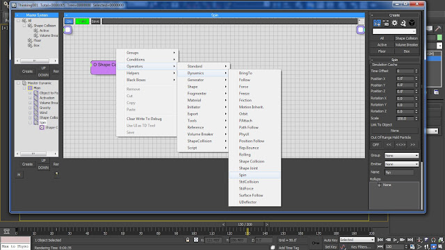
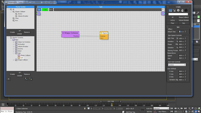
08.1 Add in a new Dynamic Set into the ‘Main’ Dynamic Set and rename it as ‘Spin’. Bring in the ‘Shape Collision’ group from the right click menu ‘Groups > Shape Collisions’. Also add in a ‘Spin’ Dynamic Operator from the right click menu ‘Operators > Dynamics > Spin.
Fig 08.1
08.2 Connect the ‘Particle’ value parameters of both ‘Shape Collision’ group and ‘Spin’ operator. Change the ‘Attack Time’ value parameter to 5 and ‘Spin Time’ to 1.0 s. Place the ‘Spin’ dynamic set above the ‘Shape Collision’ dynamic set.
Fig 08.2
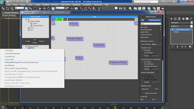
08.3 Right click on the ‘Main’ dynamic set and select ‘Cache Unset’ in order to wipe away the previous Cache information. Now select the ‘Cache Record’ from the right click menu of the ‘Main’ dynamic set and save the Cache information in the form of .tps file format from the popped up browser window.
Fig 08.3
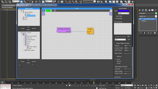
08.4 Change the ‘Color’ of the ‘Volume Breaker’ group to Blue in order to get a better visualization between them. Play back the simulation in order to see the debris in ‘Blue’ along with the ‘Red’ parts of the cardboard.
Fig 08.4
